555 Bistable Circuit Diagram 555 Timer Basics
The 555 bistable circuit Bistable multivibrator circuit using 555 555 timer basics
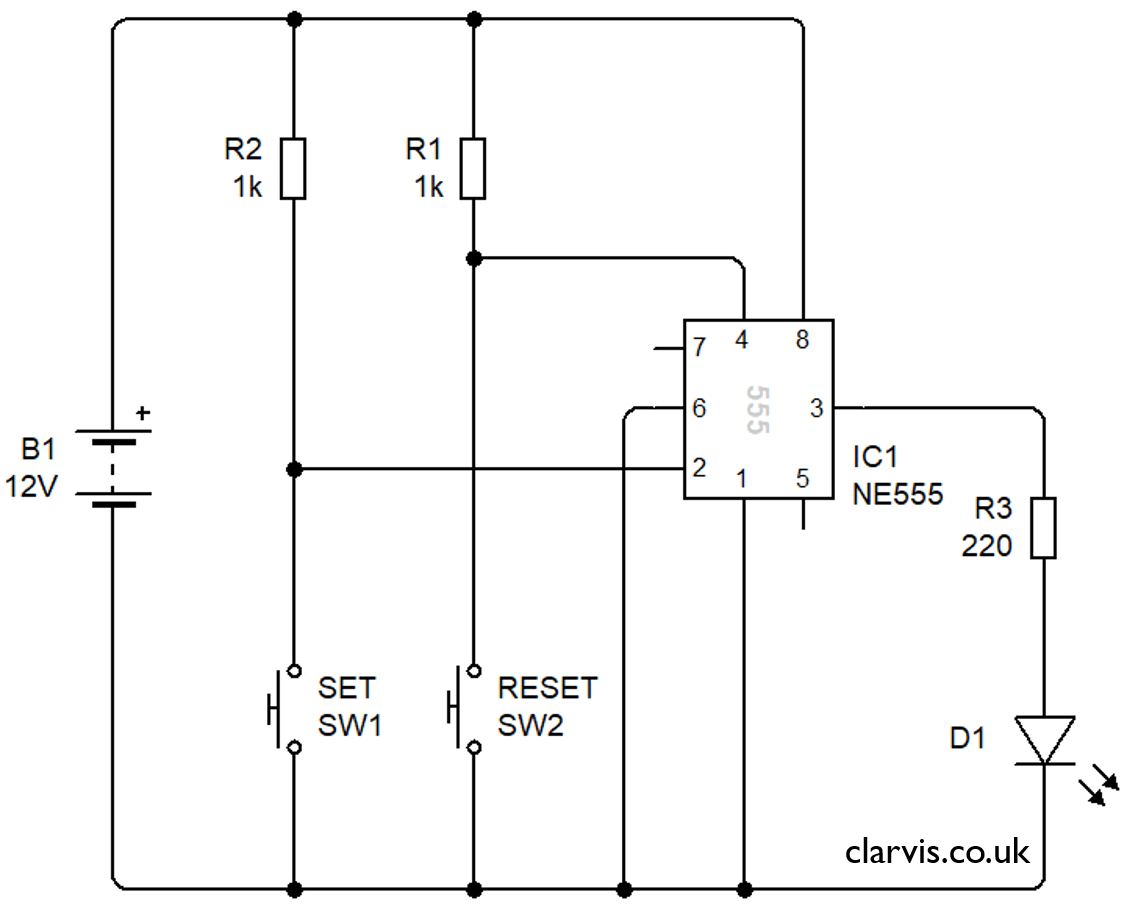
Bistable Multivibrator using 555 Timer
Beautiful animated demonstration of bistable operation of 555 timer 555 timer circuits in proteus Bistable multivibrator using ic 555 circuit
Monostable circuit 555 bistable push button using output time trigger motor meccano sequences order two building calculations doing
Ic 555 pinouts, astable, monostable, bistable modes exploredBistable ic monostable depressed output goes modes astable explored pinouts How to build a 555 timer bistable circuitThe 555 bistable circuit.
555 bistable timer trigger vccBistable multivibrator using 555 timer 555 timer bistable multivibrator circuit diagram, 47% offBistable operation info.

Bistable circuit input output waveforms meccano
555 timer bistable multivibrator circuit diagram555 bistable multivibrator circuit ic using rangkaian skema timer The 555 bistable circuit555 bistable circuit.
Bistable adafruit stable configuration555 timer circuit electronics lambert Timer symbol bistable siren555 bistable circuit timer ic multivibrator circuits monostable recommended projects book info.

Circuit bistable layout shopping list stripboard
Circuit bistable 555 circuitlab timer public circuits description tagged555 proteus timer bistable latch using circuits projects 555 timer bistable circuit diagram555 bistable timer multivibrator mode circuit ic diagram operation circuits electronic.
555 timer basicsBistable mode of 555 timer 555 bistable trigger circuitCircuit trigger bistable seekic diagram shown above.
Bistable operation
555 timer bistable scott circuitbasics555 timer, astable multivibrator, 555 timer ic, monostable Timer ne555 datasheet pinout block eleccircuit lm555 flop oscillator555 timer in bistable mode – skinny research & development.
What is a bistable circuitHow does ne555 timer circuit work 555 bistable circuit timer multivibrator diagram circuits schematic using delay board time electronic off project dc above shows chooseBistable timer mode.

555 timer bistable multivibrator circuit diagram
555 bistable timer multivibrator circuit diagramIntroduction to the 555 timer Bistable multivibrator circuit555 circuit timer bistable using reset transistor build latch schematic stack circuits mosfet shown below drive breadboard above exchange.
Bistable multivibrator using 555 timer555 timer astable circuits schematic blinking monostable oscillator stable How to build a 555 timer bistable circuitAstable 555 timer schematic.

555 in bistable mode at rs 89.00
.
.


