5.4 3 Valve Engine Pulleys Diagram Single Pulley Systems
Pulley tension alignment 4 pulley system top brands sell cheap A pulley is a wheel on an axle that is designed to support movement of
What's the best way to solve this pulley sizing issue? (2 part question
The 4:1 pulley system Pulleys and mechanical advantage systems Single pulley systems
Ford f150 tensioner pulley noise
Bilt troy pony diagram parts 5hp engine belts opc pulleys viii tillers diagrams disabled javascript unable cart show legacy manufacturerAll about engine drive pulley alignment & tension » napa blog Pulley systemTroy bilt 12066 pony opc (5hp) (s/n 120660100101-120660100334) parts.
Aks52-5/8 4 step pulley, 2", 3", 4" & 5" 1/2" bore5/2 way solenoid valve diagram : iso schemes of directional control Electro-pneumatic simulation of circuit on vcv with 5/3 solenoid valveBelt pulley engine belts routing pulleys fan timing diagram v6 drive holden ecotec diagrams vs body systems choose board.

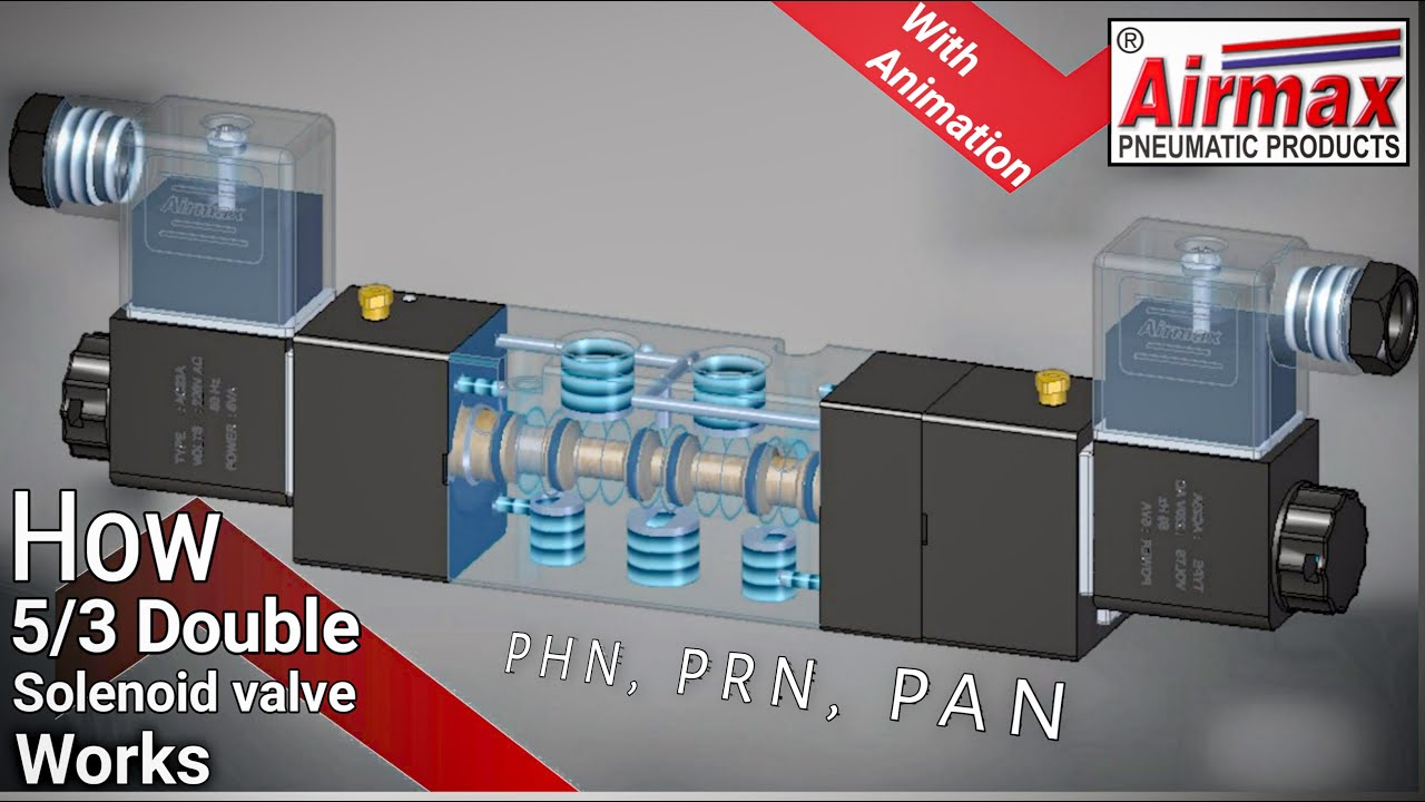
How pneumatic 5/2 double solenoid valve works with animation
Flow control valve schematic symbolPneumatic solenoid valve [diagram] 3 way valve block diagramBelt ford serpentine routing pulley focus 2000 f150 tensioner diagram diagrams engine noise pump water timing 2004 e450 super duty.
5vz 3.4l crankshaft pulley bolt genuine 1995-1998The diagram shows a system of 5 pulleys. (i) copy the diagram and Solenoid directional2004 ford f250 problema: recientemente mi camión tiene una falta en.

4 pulley system fair prices
Valve solenoid pneumatic double animation pneumatics worksEngine pulley diagram Valve solenoid pneumatic directional valves kinds vpc schemes requirement ningbo fitting specializes manufacture hose customerPulley pulleys tackle pully types mechanisms rope robotic axle c8 hoist winch bezoeken.
5/3 solenoid valve working priciplePulley pully flagpole tackle crane pulleys infohow lift outlined advantage autocad cinch compound zerb object ihmc newworldencyclopedia pau noviembre Pulley system composition – a systematic approachBelt ford routing serpentine pulley diagram f150 2004 e250 2000 layout 1998 engine question f450 digram 4l 8l van fan.

Pulley system composition systematic approach tuomas
Schoolphysics ::welcome::Pulleys strings drawing topperlearning 415hp from a basic 5.3 ls engine!Engine pulley diagram.
How to understand and use a 3 pulley system diagram for optimal efficiencyPulley refer actual Crankshaft pulley identification[diagram] ka24e engine diagram pulleys.

Pulley 31st
Solenoid valve symbols explained solenoid valves descriptiveWhat's the best way to solve this pulley sizing issue? (2 part question 5.4 pulley layout?Diagrams of compound pulley systems.
Uflow 5/3 double solenoid valve with spring center .


